


MANUAL 2D VIDEO METROLOGY — PRO6436
Manual optical coordinate measurement with CCD targeting and software reporting
The MVM3020 manual video measuring system is an entry-level industrial metrology platform for measuring lengths, diameters, radii, angles, spacing, edges and other two-dimensional geometric features. The operator positions the component on the glass stage, targets the feature on the video image and moves the manual XY stage to capture coordinates.
A 0.7–4.5× zoom lens, 92 mm working distance, 30–190× video magnification and adjustable LED surface and transmitted illumination support inspection of machined components, PCB features, tools, moulds and production parts. Measurement results can be processed by dedicated software and transferred to AutoCAD, Excel or Word.
Key characteristics
- Model: MVM-3020 · SKU PRO6436.
- XY measuring stroke: 300 × 200 mm.
- Z stroke: 150 mm.
- Scale resolution: 0.5 / 0.1 μm.
- Zoom lens: 0.7–4.5× with 92 mm working distance.
- Video magnification: 30–190×.
- Camera: 1/3-inch colour CCD with cross-line generator.
- Adjustable LED surface and transmitted illumination.
- RS-232 interface with dedicated measurement software.
Suitable for
- Machining, toolmaking and dimensional inspection.
- Hole spacing, diameter, radius and angle measurement.
- PCB and electronic component inspection.
- Automotive and aerospace quality control.
- Mould, die, profile and edge inspection.
- Repeatable 2D coordinate measurement and reporting.
- CAD-compatible output and statistical result processing.
- Industrial laboratories and production QC departments.
MVM3020 — MANUAL VIDEO MEASURING SYSTEM
Manual video measuring system for industrial 2D inspection
A manual video measuring system is selected when the operator needs controlled XY positioning, magnified video targeting and software-assisted dimensional measurement without the complexity of a fully automatic CNC vision system. MVM3020 provides a stable platform for routine 2D inspection while retaining direct manual control of the measuring stage.
The MVM3020 video microscope measuring system is particularly useful where components must be checked for lengths, diameters, radii, angles, chamfers, spacing and profile geometry. The large 300 × 200 mm measuring range supports a broad selection of parts, while the 350 × 280 mm glass table provides practical component positioning and transmitted illumination.
For documented quality-control work, measurement coordinates can be processed in the supplied software environment and exported to CAD or office reporting workflows. The final computer, software version, data card, illumination package, accessories and documentation scope must be confirmed in the approved quotation.
MVM3020 measuring platform and manual inspection workflow
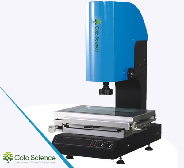
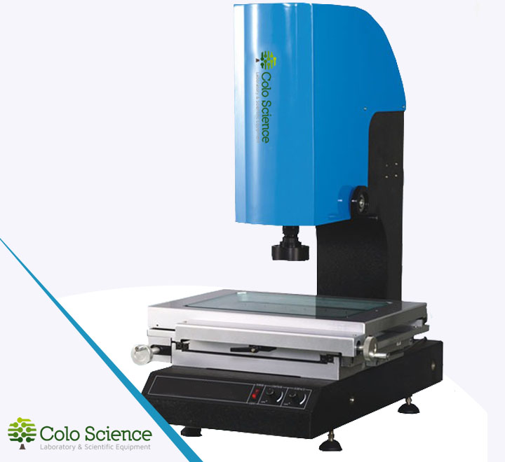
MVM3020 combines a precision manual XY stage, zoom optical head, CCD video targeting and adjustable reflected and transmitted LED illumination.
Four-step measurement workflow
- Position: place the component on the glass measuring stage.
- Target: identify the feature using the cross-line CCD image.
- Measure: move the XY stage and capture the coordinate positions.
- Process: calculate, map and export the measured geometry.
MVM3020 model selection parameters
MVM-3020 · PRO6436
XY stroke:
300 × 200 mm
Z stroke:
150 mm
Zoom / WD:
0.7–4.5× / 92 mm
Video magnification:
30–190×
Scale resolution:
0.5 / 0.1 μm
Camera:
1/3-inch colour CCD
MVM series platform context
MVM-2010
XY stroke: 200 × 100 mm
Glass table: 260 × 160 mm
Weight: 180 kg
MVM-3020 · Featured model
XY stroke: 300 × 200 mm
Glass table: 350 × 280 mm
Weight: 260 kg
MVM-4030
XY stroke: 400 × 300 mm
Glass table: 450 × 350 mm
Weight: 315 kg
MVM-5040
XY stroke: 500 × 400 mm
Glass table: 550 × 450 mm
Weight: 500 kg
This product page describes MVM3020 / MVM-3020. Other MVM platforms are shown only as series selection context and require a separate quotation.
TECHNICAL SPECIFICATIONS — MVM3020
| Product | MVM3020 manual video measuring system |
| Model / SKU | MVM-3020 / PRO6436 |
| Measurement principle | Manual optical 2D coordinate measurement |
| Metal table size | 500 × 330 mm |
| Glass table size | 350 × 280 mm |
| XY stroke | 300 × 200 mm |
| Z stroke | 150 mm |
| Zoom lens | 0.7–4.5× |
| Working distance | 92 mm |
| Video magnification | 30–190× |
| Object view | 7–1.1 mm |
| Camera | TEO™ 1/3-inch colour CCD with cross-line generator |
| Scale resolution | 0.5 / 0.1 μm |
| Accuracy E1 | Ex,y ≤ (3.0 + L/200) μm |
| Accuracy E2 | Exy ≤ (4.0 + L/200) μm |
| Illumination | Adjustable LED surface light and LED transmission light |
| Interface | RS-232 with dedicated measurement software |
| Output workflow | AutoCAD-compatible output; Excel and Word transfer |
| Power | 110/220 V AC, 50/60 Hz, 30 W |
| Dimensions | 670 × 660 × 950 mm |
| Weight | 260 kg |
L is the measured length in millimetres in the stated accuracy formula. Measurement performance depends on installation, environmental stability, component positioning, illumination, focusing, operator procedure and system configuration.
Measurement software and data workflow
Coordinate acquisition
Optical grating position feedback and the XY coordinate system support digital acquisition of manually targeted measurement points.
Geometry processing
Dedicated software supports coordinate processing, geometric calculations, circular mapping and dimensional result evaluation.
CAD and reporting
Measured geometry can be transformed into AutoCAD-compatible output and transferred to Excel or Word for statistical analysis and reporting.
Configuration confirmation
Computer, software version, data card, operating-system compatibility and delivered reporting functions should be confirmed before ordering.
TYPICAL INSPECTION APPLICATIONS
Dimensional inspection in production and quality-control environments
Machining and toolmaking
Inspection of lengths, diameters, radii, angles, chamfers, groove widths, profiles and hole spacing.
Electronics
PCB feature inspection, component geometry verification and dimensional checks during production.
Automotive and aerospace
Precision dimensional checks, geometric verification and tolerance control of manufactured components.
Mould and die work
Profile, edge, cavity and geometric feature measurement for tooling and mould inspection.
COLO.SCIENCE MICROSCOPY KNOWLEDGE
Explore microscopes and optical inspection applications
Visit COLO.Science for additional information about laboratory microscopes, optical instruments, image-based inspection and measurement applications.
How to configure the MVM3020 manual video measuring system
First define the maximum component dimensions and the features that must be measured. The 300 × 200 mm XY travel should cover the required measuring envelope, while the 92 mm working distance must provide sufficient clearance for component handling and focusing.
Next define the expected tolerance range, reporting method and software workflow. Confirm whether AutoCAD-compatible output is required, whether results will be transferred into Excel or Word, and whether the supplied computer and software configuration must follow a specific internal IT standard.
For installation planning, provide the available space, bench or floor requirements, power supply and environmental conditions. Because MVM3020 weighs approximately 260 kg, transport access, positioning and final installation should be planned before delivery.
Configuration notice
MVM3020 systems may be supplied with different computer, software, data-card, illumination, accessory and documentation configurations. The official quotation defines the final delivered system, included components, software version, reporting functions, installation scope and available certificates. Specifications may change without notice.